Symbols are the primary chart objects. A chart is a collection of symbols with optional lines between them. Symbols have the following properties:
| Location | The position of the center of the symbol, relative to the top left corner of the chart. Locations are precise to 1/1000". |
| Shape | A choice of one of the possible prototype shapes for symbol, as defined by the current shape file. Also, the thickness and style (solid, dash, dot) of the border of the symbol, and an indication of which plane the symbol is drawn in. |
| Size | The height and width of the rectangle bounding the symbol. Measurements are precise to 1/1000". |
| Text | The text displayed inside the symbol. Also, the fonts used by that text, and how that text is positioned (justified) within the symbol. |
| Color | The colors used to draw the border, background and text of a symbol. |
| Picture | An optional bitmap or metafile picture that is displayed to fit within the text area of the symbol. In Chartist-Pro, the picture may also be an OLE object. |
| Reference | An optional command line to display a reference document associated with the symbol. In Chartist-Pro, the reference may also be an OLE object. |
| Orientation | The orientation of the shape, relative to its basic definition. Shapes can be rotated in 90 degree increments, and flipped horizontally and vertically. |
| Text Angle | The angle of the text in the symbol, relative to horizontal. Chartist-Pro |
When symbols are added to the chart, they take on the current default settings for each of the properties that are not explicitly defined during the add operation.
To add a symbol to the chart,
click on the ![]() button in the Tool Bar, select the Symbol Add... command
from the menu, or press the Ins key. The cursor will
change to the box shape. Move the cursor to the grid point where
you want the symbol centered, and click or press Enter.
button in the Tool Bar, select the Symbol Add... command
from the menu, or press the Ins key. The cursor will
change to the box shape. Move the cursor to the grid point where
you want the symbol centered, and click or press Enter.
You may cancel an Add operation in progress by pressing Esc.
Otherwise, a dialog box appears: Symbol Properties. See Figure 4-1. You will see a multi-column list box with symbol type names in it. If the current shape file has a large number of symbol types, there may be a scroll bar on the list box to assist you. As you move the list box selection cursor, notice that the selected shape is drawn to the right of the list box at 1/2 normal size.

Figure 4 - 1
Select Symbol Shape Dialog
Note that a few shapes appear to have no representative model. These are text only shapes, such as Titles. The borders of these shapes are visible only when they are displayed in the chart.
The border thickness and style may also be selected, using the appropriate radio buttons.
The Orientation of the symbol may also be selected. Symbols may be rotated in 90 degree increments counterclockwise from their defined orientation. They may also be flipped about their horizontal or vertical axes.Chartist-Pro
Finally, the Plane of the symbol may be selected. Symbols in the Bottom plane are drawn first, followed by symbols in the Middle plane, then by symbols in the Top plane. This feature supports visual effects such as layering symbols and framing symbols with other symbols.
Select the desired shape properties and click the OK button (or Enter). A new symbol with the selected properties will be added to the chart at the chosen location.
Clicking on Cancel will stop the Add procedure.
If the Shape Palette is visible (View Shape Palette is checked), then new symbols may be added by clicking on the desired new shape in the Shape Palette and then moving the cursor as above to the desired location for the new symbol, and clicking the mouse once more. The new symbol is added with the desired shape. All other properties are determined by the default settings for new symbols.
Symbols in the chart may only be operated on when they are selected. When a symbol is selected, it is surrounded by eight selection handles, or a dotted rectangle if multiple symbols are selected.
Some commands require that only one symbol be selected, while others require or allow more. Menu commands are enabled when the number of selected symbols is correct for their respective actions.
1. Place the cursor inside the symbol and click the mouse (or press Enter).
or,
2 Choose the Symbol Select command (F7). The gunsight cursor will appear. Click on a point outside but near the symbol(s) to be selected. The cursor will change to the quad arrow. Drag the selection rectangle to touch or include the symbol(s). See Figure 4-2. Click again to complete the process.
or,
3. Click and hold the left mouse button with the cursor outside but near the symbol(s) to be selected. The cursor will change first to the gunsight shape. Drag the cursor to stretch a selection rectangle as in 2 above. The cursor will change to the quad arrow when it starts to move. Release the cursor to complete the selection.
When one or more symbols is selected, the selection of any other symbols in the chart will be dropped. If you hold the Shift key down while selecting, the previous selections will be retained.
Figure 4-2
The Appearance of One and Multiple Selected Symbols
To add or remove an additional symbol to/from a selected group, hold down Ctrl+Shift and click the mouse inside the symbol. This will toggle the selected state of that symbol.
All items may be deselected by clicking on a point outside any symbols and away from any lines.
All symbols may be selected by choosing the Symbol Select All (Ctrl+F7) command.
The Symbol Select To End commands can be used to select all symbols from the coordinate of the current selected symbol to the end of the chart in the indicated direction (Right, Left, Up, Down).
You may change the shape of one or
more symbols at any time. Select the symbols to change and click
on the ![]() Tool
Bar button, or choose the Symbol Properties... command (F4).
You will see the Select Symbol Shape dialog box. See Figure 4-1.
Tool
Bar button, or choose the Symbol Properties... command (F4).
You will see the Select Symbol Shape dialog box. See Figure 4-1.
If no symbols are selected, the current default settings for shape properties will be selected for modification.
If multiple symbols are selected, the common properties will be shown as selected in the dialog. Any properties modified in the dialog will be applied to the selected symbols.
Choose new shape properties and click the OK button or press Enter.
Alternatively, a symbolÆs shape can be changed to one of those on the shape palette by first selecting the symbol(s) and then holding down the shift key while clicking on one of the symbols in the shape palette.
In addition to the Symbol Properties... command mentioned above, you may use the Symbol Rotate (Ctrl+R) command to rotate one or more selected symbols by 90 degrees counter clockwise. Also the Flip X (Ctrl+Shft+X) and Flip Y (Ctrl+Shft+Y) commands will flip the selected shape or shapes about the indicated axes.Chartist-Pro
Double-click the mouse on the desired symbol (if there is no picture object in the symbol), or with only the desired symbol selected, choose Symbol Text Edit... (F3). The Edit Symbol Text dialog box is displayed. The area for text entry operates similarly to other Windows applications. See Figure 4-3.
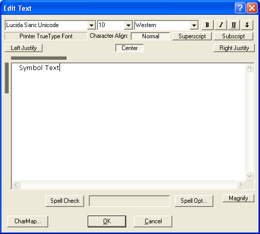
Figure 4-3
Edit Symbol Text
The text edit area appears within the Edit Symbol Text dialog box. Any text in the symbol is displayed in this area and may be edited. The size of the green rectangle agrees with the boundary for text in the selected symbol, at 100% scale. If the text exceeds the boundary, that part of the boundary is shown in red. If a very small font is being used, the text area can be shown at 2X normal scale by checking Magnify. Text in a symbol is automatically word wrapped.
The caret is a flashing vertical bar. It represents the insertion or deletion point for changes. The caret may be moved through the text, as described below in Edit Text Actions.
Selected text is indicated in reverse video. When there is selected text, the whole selection is subject to deleting, re-fonting, copying or cutting to the Clipboard.
Table 4-1
| Key/Mouse | Action |
| Normal Key | Character is inserted into the text at caret. Any selected text is deleted |
| Arrow Key | Removes any selection and moves caret. |
| Shift+Arrow | Adds character to selected text. |
| Ctrl+Left / Right Arrow | Moves caret to beginning of word. |
| Shift+Ctrl+Left / Right Arrow | Adds word to selected text. |
| Home | Removes any selection and moves caret to start of line. |
| End | Removes any selection and moves caret to end of line. |
| Shift+End | Selects text to end of line. |
| Ctrl+End | Removes any selection and moves caret to end of text. |
| Shift+Ctrl+End | Selects all remaining text. |
| Del | Clears any selected text, or deletes character after caret. |
| Ctrl+X or "Cut" button | Cuts selected text to Clipboard, or deletes character after caret. |
| Ctrl+V, or "Paste" button | Pastes text from Clipboard, starting at caret. Any selected text is deleted. |
| Ctrl+C, or "Copy" button | Copies selected text to Clipboard. |
| Enter | Inserts a new line at caret. Any selected text is deleted. |
| Mouse left button | Moves caret to cursor and drops selection anchor. |
| Mouse left double click | Selects word at cursor and moves caret to end of word. |
| Shift+Mouse left button | Moves caret to cursor and selects intervening text. |
| Drag (Click and hold Mouse left button) | Drops selection anchor, moves caret to cursor, and selects intervening text. |
Text from other applications may be pasted into the text area. Simply Copythe text into the Clipboard from the other application, and then Paste it into the text area. Formatting information is copied if it is available.
When data is cut or copied to the Clipboard, previous data is always cleared.
The Left, Center and Right radio buttons along the top of the Edit Text area, let you choose how the text is justified horizontally in the symbol.
The justification of text in a
symbol may also be changed from the main window. Select the
desired symbols and click on the desired justify buttons, ![]() , in the Tool
Bar or use the Justify commands. the selected symbols with
be changed to the new justification.
, in the Tool
Bar or use the Justify commands. the selected symbols with
be changed to the new justification.
Characters that do not appear on your keyboard may be entered with the Keymap button. This button brings up a dialog that allows you to select a character from a scrollable list of all of the characters in the selected font.
To finish editing click the OK button with the mouse, or press Alt+O. The symbol will appear with the new text inside it.
A new symbol uses the last selected font for text. If more text is placed in a symbol than will fit, it is clipped when displayed in the chart, but remains in the symbol.
Certain text strings can be placed in symbols that will cause the time and date to be displayed. When viewing from the Edit Text dialog, you see these text strings. When viewing from the main window, or printing, you see the time or date. To use one of these macros, place the string, exactly as shown, in the symbol.
| Macro String | Meaning |
| @FDATE_M | The last date the document was saved (US Format) |
| @FDATE_D | The last date the document was saved (European Format) |
| @CDATE_M | The current date (US Format) |
| @CDATE_D | The current date (European Format) |
| @FTIM | The last time at which the document was saved |
| @CTIM | The current time |
Certain text strings can be placed
in symbols that will cause the document name and symbol number to
be displayed. The document name is the first part of the file
name of the document. The symbol number is the internal reference
number given to a symbol to make it unique. When viewing from the
Edit Text dialog, you see these text strings. When viewing from
the main window, or printing, you see the time or date. To use
one of these macros, place the string, exactly as shown, in the
symbol.
| Macro String | Meaning |
| @DOCNAME | The name of the document |
| @SYMNUM_ | The symbol number, no leading zeroes |
| @SYMNUM0 | The symbol number, with leading zeroes |
| @PAGNUM_ | The page number, based on printing order (X or Y first), leading blanks |
| @PAGNUM0 | The page number, with leading zeroes |
The @DOCNAME macro, when used in an embedded Chartist-Pro object, uses the name of the host document. Also, if this macro is used on systems with Long File Name support, it can be padded with trailing "@" characters to allow the entire name to be seen. Chartist-Pro
Symbols can be selected by searching for the text that they contain. Also, text in one or more symbols can be replaced with other text.
Figure 4-4
Edit Find Dialog
To locate and select a symbol that contains certain text, use the Edit Find... dialog, Figure 4-4. Type the desired string into the Find What field, and click on the Match Case check box if desired. Then click on the Find Next button to find the next symbol that contains the text. Symbols are scanned in the order that they were created. If a symbol is located that is not currently in the main window, the document will be scrolled to make it visible.
This dialog remains on the screen until you click on the Cancel button.Chartist-Pro
Figure 4-5
Edit Replace Dialog
To locate and optionally replace text in one or more symbols, use the Edit Replace... dialog, Figure 4-5. As above, to locate the desired string, enter it into the Find What field. Click on the Find Next button to locate the next symbol containing the string. If a replacement is desired, click on the Replace button. To replace the string in all symbols that contain it, click on the Replace All button.
This dialog remains on the screen until you click on the Cancel button.Chartist-Pro
Select the symbol whose fonts you want to choose or modify, and choose the Symbol Text Edit ... command. With the Edit Symbol dialog box displayed, move the caret in the text area to the desired location to start a new font, or select the text to be "re-fonted." See Table 4-1 for how to select text. Then use the formatting bar at the top of the dialog to select the Font, Size and Emphasis for the text.
The list of fonts represents all fonts directly supported by the printer. Notice the buttons for font emphasis: Bold, Italic, Strike Out and Underline. You may choose these options. If your printer does not support these options directly, Windows will simulate the font instead of using the printer font.
The font properties currently in use at the cursor, or in the selected text will be shown as selected in the dialog box. If an area is selected where font characteristics vary, only those that are in common will be shown as selected. If emphasis varies, the emphasis check buttons will be "grayed".
Those font properties that are changed during the dialog will be applied to the selected text. This means that you can, for example, change the type size of selected text without changing the emphasis, which may vary within the selected area.
Depending on your display resolution, small fonts may not be legible in the edit text area. The Edit Symbol Text dialog box provides a Magnify check box to allow editing of small fonts. Checking this box will cause the text area of the symbol being edited to display at 2X normal size.
When one or more symbols are selected, the fonts in those symbols may be changed as a group, or reduced or enlarged as a group.
To modify font properties of a
group of symbols, select the symbols, then choose the Symbol
Text Font.. (Ctrl+F) command, or click on the ![]() button in the
Tool Bar. The Choose Font dialog, as described above, will be
displayed. Any changes made to the font properties will be
applied to all selected symbols, as if all text in those symbols
were selected.
button in the
Tool Bar. The Choose Font dialog, as described above, will be
displayed. Any changes made to the font properties will be
applied to all selected symbols, as if all text in those symbols
were selected.
To enlarge or reduce the
size of the text in the selected symbols, choose the Symbol
Text Enlarge (Alt +, or ![]() ), or Symbol Text Reduce
(Alt -, or
), or Symbol Text Reduce
(Alt -, or ![]() ) command. The fonts in the selected
symbols will change by 2 points. Chartist-Pro
) command. The fonts in the selected
symbols will change by 2 points. Chartist-Pro
Text in a symbol may be
rotated in 90 degree increments. To set the angle of text
in one or more symbols, select the symbols and choose the
Symbol Text Angle (Ctrl+A, or ![]() )
command. The Set Text Angle dialog will appear. See
Figure 4-7. Choose the desired text angle for the
selected symbol(s) and click on OK to complete the
command. Chartist-Pro
)
command. The Set Text Angle dialog will appear. See
Figure 4-7. Choose the desired text angle for the
selected symbol(s) and click on OK to complete the
command. Chartist-Pro
Figure 4-7
Set Text Angle Dialog
The symbol reference is a command string,
or linked or embedded OLE object Chartist-Pro
to display a reference document. Such a reference can be displayed by selecting the View Reference (Shift F3) command or double-clicking on the symbol with the Ctrl key held down. This behavior is similar to that of hypertext. When a symbol has a reference established, an asterisk (*) will de displayed in the lower right corner of the symbol, in the text color used by the symbol and in the current line font. The asterisk does not show in data sent to the clipboard nor when the Chartist document is printed.
To establish or modify a symbol
reference, select the symbol and then choose the Symbol
Reference... command (Ctrl+F4), or click on the ![]() button in the
Tool Bar. The Edit Symbol Reference dialog box will be displayed.
See Figure 4-8.
button in the
Tool Bar. The Edit Symbol Reference dialog box will be displayed.
See Figure 4-8.
Figure 4-8
Edit Symbol Reference Dialog
Enter the command string for the reference document into the edit field. File names for documents should be fully qualified with the path name.
If an object is in the clipboard, the Paste button will be enabled. Click on the Paste button to embed the object.
If a linkable object is in the clipboard, the Paste Link command will be enabled. Click on the Paste Link button to link the object.
To insert a new embedded object, click on the Insert... button. The Insert Object dialog will appear. Choose one of the objects. The application for that object will be activated, and you will be able to create the new object and insert it into the symbol reference.
The Action... button activates the object, or in the case of objects with multiple verbs, brings up a list of verbs that are available for activation.
The Clear button removes the symbol reference.Chartist-Pro
To view a symbol reference, select the desired symbol and choose the View Referencecommand (Shift F3), or hold down the Ctrl key and double-click on the symbol. If a reference has been properly established, the application that displays the document will activate with the reference document loaded. Chartist becomes inactivated at this point, until you re-activate it. The reference document application will remain active until you close it or activate another application.
A symbol can display a picture in its text area. The picture may be stretched or shrunk to fit inside the symbol. Pictures may be device independent bitmaps (.bmp) files, metafiles (.wmf), metafile pictures from the clipboard,
or OLE linked or embedded objects that provide metafile picture data.Chartist-Pro
To add a picture to a symbol,
select the desired symbol and choose the Symbol Picture...
command (Shift+F4) or click on the ![]() button in the
Tool Bar. The Edit Symbol Picture dialog box will appear,
Figure 4-9. Any picture already in the symbol will be displayed
in the dialog box.
button in the
Tool Bar. The Edit Symbol Picture dialog box will appear,
Figure 4-9. Any picture already in the symbol will be displayed
in the dialog box.
Figure 4-9
Edit Symbol Picture Dialog
To remove a picture, click on the Clear button.
Checking the Stretch to Fit checkbox, will cause the picture to be stretched or shrunk to fit exactly within the symbol. Otherwise the picture will be displayed in its original size and clipped if necessary.
For files:
To load a new picture from a file, click on the Load button. The Open File dialog will be displayed, with the default extensions set to .WMF and .BMP which will display .BMP and .WMF files. Select the desired file by double-clicking on it in the list box, or by typing in the file name and clicking on Open. The selected picture will be loaded into the symbol.
Figure 4-10
Opening A Picture File
Click on the Picture button, if it is enabled. The metafile picture in the clipboard will be loaded and shown in the preview area.
For OLE objects:If an object is in the clipboard, the Object button will be enabled. Click on the Object button to embed the object.
If a linkable object is in the clipboard, the Link command will be enabled. Click on the Link button to link the object.
To insert a new embedded object, click on the Insert... button. The Insert Object dialog will appear. Choose one of the objects. The application for that object will be activated, and you will be able to create the new object and insert it into the symbol picture.
The Action... button activates the object, or in the case of objects with multiple verbs, brings up a list of verbs that are available for activation.
The Update button is enabled if the symbol contains a linked object. Clicking on Update will obtain the latest picture data from the source document.Chartist-Pro
If the View Pictures command is checked all symbol pictures will be displayed. Unchecking the View Pictures command causes all symbol pictures to be shown as gray rectangles, speeding up the display process considerably if there are pictures.
Stretch or shrink the symbol to get the desired size and aspect ratio for the picture. Depending on how the picture was digitized, it may look distorted on the display.
If there is also text in a symbol, it is displayed on top of the picture.
Note: It is easy to create framed and titled pictures, for example, of members of an organization. See the Chapter 8: Tips and Techniques.
When a picture is loaded in this manner, it is incorporated into the Chartist document. The picture data is preserved in its original form. This means that the picture will take full advantage of any display or printer that it is drawn onto from Chartist. Pictures are displayed as gray rectangles when the View Pictures command is unchecked (to save display time).
Select the symbols that you want to delete, then choose the Edit Delete (Del) command. All selected symbols and all lines connected to those symbols are deleted from the chart.
Changes made to symbols and lines can be undone with the Edit Undo (Ctrl+Z) command. Pull down the Edit menu to see if the Undo command is available for undoing the last change.
Copying replicates the selected symbols and connected lines and places that information into the Clipboard. Once in the Clipboard the data may be pasted as a unit back into the chart, into a different chart, or into other applications.
Select the symbols to copy, and choose the Edit Copy command (Ctrl+C). The operation will complete. Any information already in the Clipboard will be overwritten.
Cutting symbols means to remove them from the chart and place them into the Clipboard. Once in the Clipboard the symbols may be pasted as a unit back into the chart, into a different chart, or into other applications.
Select the symbols to be cut, then choose the Edit Cut command (Ctrl+X). The selected symbols and any lines connected between them will be placed into the Clipboard. Then the selected symbols and all lines connected to them will be deleted from the chart.
Note that lines that no longer have a source or destination are removed from the chart, but if the each end of the line is not connected to one of the cut symbols, it will not be copied to the Clipboard.
Figure 4-11
Bounding Box For Moving Or Pasting Symbols
If the Clipboard contains Chartist symbol data, the Edit Paste command (Ctrl+V) is made active (not grayed). To paste, select the command. The cursor will change to the box shape.
When you move the cursor, a dashed rectangle will surround the cursor and track its movements, to show you the shape and extent of the area to be pasted. See Figure 4-11. This dashed rectangle bounds the symbols to be added. Click the mouse, or press Enter to complete the operation.
The operation will fail if you attempt to add symbols outside the boundaries of the chart. The chart boundaries are set with the Options Chart... command.
When symbols are pasted, they are selected, and any other selections are dropped.
You may move symbols one at a time, or as a group. Select the symbols to move, and:
The cursor will change to the box shape.
When you move the cursor, a dashed rectangle will surround the cursor and track its movements, to show you the shape and extent of the area to be moved. See Figure 4-11. This dashed rectangle bounds the symbols to be added. Click the mouse, or press Enter to complete the operation.
The selected symbols move as a group, and maintain their relative locations with respect to one another. All lines are rerouted as required, and remain connected to their sources and destinations.
This operation will fail if you try to place symbols outside the chart boundaries. The chart boundaries are set with the Options Chart... command.
One or more symbols can be replicated with a special click and drag operation. First, select the symbol or symbols desired. Then, hold down the Ctrl key, and click inside one of the selected symbols and drag the selection to the desired location. The selection will be replicated at the desired location.
New symbols are added to the chart at the current default symbol size.
You are not restricted to this default symbol size, however, and are free to change the size of any symbol.
You may select a default size for new symbols. Once you select a default size, all new symbols that you add from that point will start out being that size. Symbols already in the chart are not affected.
To change the default symbol size,
click on the ![]() button in the Tool Bar, or choose the Options Default Symbol
Size... command. You will see the Set Default Symbol Size
dialog box. See Figure 4-12.
button in the Tool Bar, or choose the Options Default Symbol
Size... command. You will see the Set Default Symbol Size
dialog box. See Figure 4-12.
You may choose 50% or 100% standard size with the push buttons, or you may select a symbol prior to choosing the command, and copy the dimensions of that symbol. The standard size for symbols is 1.250" wide by 0.750" high. You may override the standard size dimensions with the Options Misc Settings dialog. Refer to Chapter 7: Options.
You may enter a height and width directly as well. When this command is completed, all new symbols will be scaled to the new default size.
Figure 4-12
Set Default Symbol Size
Symbols may be set to the current
default size at any time. Select the desired symbols, and click
on the ![]() button in the Tool Bar, or choose the Symbol Reset Size command
(Shift+F6). All selected symbols will change to the
current default size setting.
button in the Tool Bar, or choose the Symbol Reset Size command
(Shift+F6). All selected symbols will change to the
current default size setting.
The size of any symbol may be changed by stretching.
To stretch a symbol, select it and:
1. Move the mouse cursor over one of the eight sizing handles on the selected symbol. The cursor will change to a double arrow when it is over a handle. Click and drag the handle of the symbol to the new size.
or,
2. Choose the Symbol Size... command (F6). The cursor will change to the quad arrow and move to the lower right corner of the symbol's bounding rectangle. Move the cursor to change the symbol size. When you have the symbol at the desired size, click the mouse or press Enter to complete the stretching.
If you hold down Shift while stretching, the aspect ratio of the symbol will remain constant.
If you hold down Ctrl while stretching, the symbol will stretch from the corner or side opposite the cursor. Otherwise, the symbol will stretch about its center. See Figure 4-13.
Figure 4-13
Stretching a symbol
You may also stretch a group of symbols with the Symbol Size (F6) command. Select the desired symbols then press F6 to activate the command. As above the cursor will change to the quad arrow and move to the lower right hand corner of the selected group. Move the cursor as desired to size the bounding rectangle for the group. When you click the mouse again, the selected symbols will change to fit within the new bounding rectangle.
If you hold down the Alt key while stretching the group, the symbols will not change size, but the distance between them will change.Chartist-Pro
You may want to change the size of text in the symbols (Symbol Text Reduce / Enlarge), or you may want to "re-snap" the symbols onto grid points (Symbol Align To Grid) to clean up the appearance of a re-sized group.Chartist-Pro
After re-sizing a group of symbols, or if Options Snap To Grid is turned off, you may need to re-center symbols onto grid points. Select the desired symbols and choose the Symbol Align To Grid (Ctrl+S) command. All selected symbols will be snapped to the nearest grid point. The grid spacing is set with the Options Chart... command.Chartist-Pro
To align a group of symbols into a column or row, select the symbols to align, and choose the Symbol Align Column or Symbol Align Row command. The chosen symbols will align their centers to match that of the topmost or leftmost symbol in the selected group.Chartist-Pro
To select colors for symbols,
click on the ![]() button in the Tool Bar, or choose the Symbol Properties...
command (F4),
button in the Tool Bar, or choose the Symbol Properties...
command (F4),
When no symbols are selected, the colors for new symbols are edited. The colors for new symbols are shown in the Tool Bar, just to the right of the buttons.
When multiple symbols are selected, the common color elements are shown. Color elements that differ among the selected group are shown as gray, unless they are changed during the Color dialog.
The Edit Symbol Colors dialog is displayed. See Figure 4-14.
Figure 4-14
Edit Symbol Colors
A sample symbol is shown in the currently selected colors.
Each of the buttons represents an element of a symbol that can be a unique color. By clicking on each button, you can change the color selection of that element.
If the Transp. box is checked, then the symbol background is not painted, making the symbol transparent.
Symbols may be filled with one of six standard hatch patterns. The hatch pattern will have the symbol background color as its background, and the symbol border color as the color of the hatch lines.
When one or more symbols are selected, the hatch pattern for those symbols may be chosen. When no symbols are selected, the default hatch pattern for new symbols is chosen.
Choose Symbol Properties... command. The Choose Hatch Pattern dialog will appear. See Figure 4-15. The selected pattern is highlighted. Click on the desired hatch pattern, and then click on the OK button to complete the operation.
Figure 4-15
Choose Hatch Pattern Dialog